An AC voltmeter measures the voltage in an alternating current (AC) circuit. Unlike a DC voltmeter, which measures a constant voltage, an AC voltmeter is designed to handle the continuously changing polarity of AC. Most AC voltmeters, especially analog ones, achieve this by converting the AC signal into a DC signal that can be measured by a sensitive direct current meter movement. Single-Phase AC Voltmeters Single-phase AC voltmeters are used to measure the voltage in circuits where the current and voltage alternate in a single, sinusoidal waveform. These are the most common type of voltmeter for household and small-scale industrial applications. Working Principle Since most meter movements, such as the Permanent-Magnet Moving Coil (PMMC) type, are designed for DC, they can't directly measure AC because the needle would simply oscillate rapidly and indicate an average of zero. To overcome this, AC voltmeters often incorporate a rectifier circuit. The rectifier converts the AC voltage into a pulsating DC voltage. The meter's internal components, which have some inertia, then mechanically average this pulsating DC, and the scale is calibrated to display the Root-Mean-Square (RMS) value of the AC voltage. The RMS value is the equivalent DC voltage that would produce the same amount of heat in a resistive load. For a pure sine wave, the relationship between peak voltage (Vm) and RMS voltage (VRMS) is VRMS=Vm/2 . Types of Single-Phase AC Voltmeters • Rectifier-Type: This is a common type that uses a rectifier circuit to convert AC to DC. The output is then measured by a PMMC meter. • Moving-Iron Type: This type of meter uses the magnetic field produced by the current flowing through a stationary coil to attract a movable iron vane, causing a deflection. The force of attraction is always in the same direction, regardless of the current's polarity, making it suitable for both AC and DC measurements. • True RMS Voltmeter: More sophisticated digital voltmeters are designed to accurately measure the true RMS value of any AC waveform, not just pure sine waves. They often use thermal conversion or complex electronic circuits to determine the heating effect of the voltage. Three-Phase AC Voltmeters A three-phase power system consists of three separate AC voltages of the same frequency, but each is 120 degrees out of phase with the others. This system is commonly used for transmitting large amounts of power and for heavy-duty industrial equipment. Measuring Three-Phase Voltage Measuring voltage in a three-phase system involves measuring two types of voltage: • Line-to-Line Voltage (VLL): This is the voltage measured between any two of the three phase lines (e.g., Phase A and Phase B). • Line-to-Neutral Voltage (VLN): This is the voltage measured between a phase line and the neutral point, if the system has one. The relationship between line-to-line and line-to-neutral voltage in a balanced three-phase system is given by the formula: VLL=3 ×VLN. Working Principle For basic measurements, you can use a standard single-phase AC voltmeter or a multimeter to measure the voltage between any two points. To get the line-to-line voltage, you would connect the probes between any two-phase wires. To find the line-to-neutral voltage, you connect one probe to a phase wire and the other to the neutral wire. Some specialized three-phase voltmeters are designed to measure all three line-to-line or line-to-neutral voltages simultaneously, often with a dedicated display for each phase, to quickly check for voltage imbalances. These devices often include multiple internal meter movements or a microprocessor to handle the three separate inputs and display the readings. FEATURES:- • Display Line to Line Voltage & Line to neutral • Password protected • Auto/Manual scrolling of parameters • RS-485 communication optional Available dimension (mm) 96x96, 72x72, 48x96, #sparkelectric #panelmeters #digital meters #l& t #selec #multispan #schneider

This is your website preview.
Currently it only shows your basic business info. Start adding relevant business details such as description, images and products or services to gain your customers attention by using Boost 360 android app / iOS App / web portal.
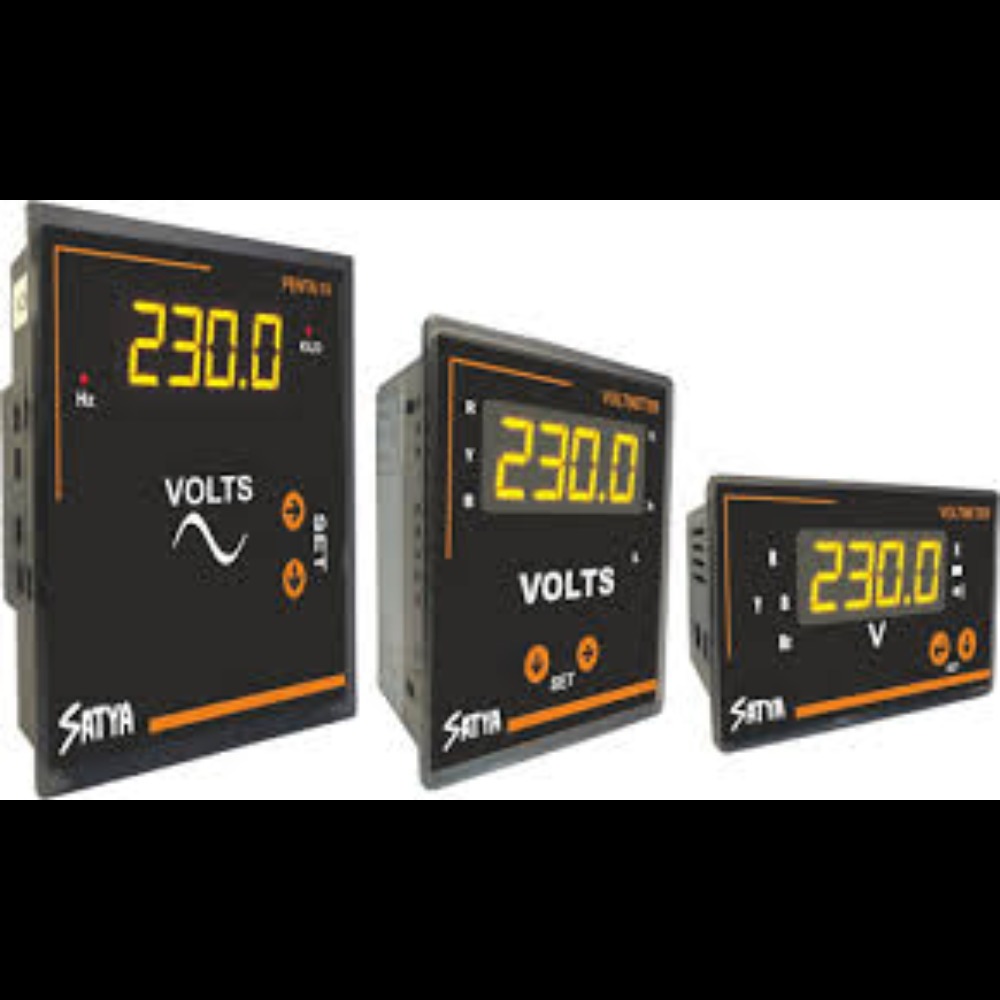
AC VOLTMETER SINGLE PHASE / THREE PHASE AVAILABLE IN NOIDA & DELHI NCR >>>>>>>>
2025-08-08T09:11:38
An AC voltmeter measures the voltage in an alternating current (AC) circuit. Unlike a DC voltmeter, which measures a constant voltage, an AC voltmeter is designed to handle the continuously changing polarity of AC. Most AC voltmeters, especially analog ones, achieve this by converting the AC signal into a DC signal that can be measured by a sensitive direct current meter movement. Single-Phase AC Voltmeters Single-phase AC voltmeters are used to measure the voltage in circuits where the current and voltage alternate in a single, sinusoidal waveform. These are the most common type of voltmeter for household and small-scale industrial applications. Working Principle Since most meter movements, such as the Permanent-Magnet Moving Coil (PMMC) type, are designed for DC, they can't directly measure AC because the needle would simply oscillate rapidly and indicate an average of zero. To overcome this, AC voltmeters often incorporate a rectifier circuit. The rectifier converts the AC voltage into a pulsating DC voltage. The meter's internal components, which have some inertia, then mechanically average this pulsating DC, and the scale is calibrated to display the Root-Mean-Square (RMS) value of the AC voltage. The RMS value is the equivalent DC voltage that would produce the same amount of heat in a resistive load. For a pure sine wave, the relationship between peak voltage (Vm) and RMS voltage (VRMS) is VRMS=Vm/2 . Types of Single-Phase AC Voltmeters • Rectifier-Type: This is a common type that uses a rectifier circuit to convert AC to DC. The output is then measured by a PMMC meter. • Moving-Iron Type: This type of meter uses the magnetic field produced by the current flowing through a stationary coil to attract a movable iron vane, causing a deflection. The force of attraction is always in the same direction, regardless of the current's polarity, making it suitable for both AC and DC measurements. • True RMS Voltmeter: More sophisticated digital voltmeters are designed to accurately measure the true RMS value of any AC waveform, not just pure sine waves. They often use thermal conversion or complex electronic circuits to determine the heating effect of the voltage. Three-Phase AC Voltmeters A three-phase power system consists of three separate AC voltages of the same frequency, but each is 120 degrees out of phase with the others. This system is commonly used for transmitting large amounts of power and for heavy-duty industrial equipment. Measuring Three-Phase Voltage Measuring voltage in a three-phase system involves measuring two types of voltage: • Line-to-Line Voltage (VLL): This is the voltage measured between any two of the three phase lines (e.g., Phase A and Phase B). • Line-to-Neutral Voltage (VLN): This is the voltage measured between a phase line and the neutral point, if the system has one. The relationship between line-to-line and line-to-neutral voltage in a balanced three-phase system is given by the formula: VLL=3 ×VLN. Working Principle For basic measurements, you can use a standard single-phase AC voltmeter or a multimeter to measure the voltage between any two points. To get the line-to-line voltage, you would connect the probes between any two-phase wires. To find the line-to-neutral voltage, you connect one probe to a phase wire and the other to the neutral wire. Some specialized three-phase voltmeters are designed to measure all three line-to-line or line-to-neutral voltages simultaneously, often with a dedicated display for each phase, to quickly check for voltage imbalances. These devices often include multiple internal meter movements or a microprocessor to handle the three separate inputs and display the readings. FEATURES:- • Display Line to Line Voltage & Line to neutral • Password protected • Auto/Manual scrolling of parameters • RS-485 communication optional Available dimension (mm) 96x96, 72x72, 48x96, #sparkelectric #panelmeters #digital meters #l& t #selec #multispan #schneider
2025-08-08T09:11:38

Keywords
- Digital voltmeter with RS-485 communication
- Multi-phase power system voltage measurement
- Industrial AC voltmeter solutions Noida
- Moving-iron AC voltmeter working principle
- Analog rectifier-type AC voltmeter
- Line-to-line and line-to-neutral voltage measurement
- True RMS AC voltmeter digital
- Three-phase AC voltmeter with display
- Single-phase AC voltmeter measuring voltage
- AC voltmeter manufacturer Noida Delhi NCR
Submit Your Enquiry