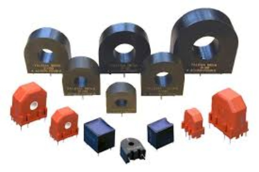
A Current Transformer (CT) is an electrical device used to measure or monitor high alternating currents safely by transforming them into a smaller, proportional current that instruments can handle. What a Current Transformer Does Converts high current in a power line (hundreds or thousands of amps) into a low current (usually 1 A or 5 A). Allows ammeters, energy meters, and protection relays to work safely. Provides electrical isolation between high-voltage circuits and measuring devices. Basic Construction Primary winding: Often just one turn (the conductor passing through the CT). Secondary winding: Many turns of fine wire connected to meters or relays. Core: Made of laminated silicon steel or ferrite to reduce losses. Working Principle Based on electromagnetic induction. AC current in the primary produces a magnetic flux in the core. This flux induces a proportional current in the secondary winding. 𝐼 𝑝 𝐼 𝑠 = 𝑁 𝑠 𝑁 𝑝 I s I p = N p N s Where: 𝐼 𝑝 I p = Primary current 𝐼 𝑠 I s = Secondary current 𝑁 𝑝 N p = Primary turns 𝑁 𝑠 N s = Secondary turns Types of Current Transformers Measuring CT Used with ammeters and energy meters. High accuracy under normal load. Protection CT Used with relays and circuit breakers. Designed to work accurately during fault conditions. Construction Types Wound CT Bar-type CT Ring / Window CT Split-core CT (can be installed without disconnecting the conductor) CT Ratings (Important Parameters) Current ratio (e.g., 100/5 A) Burden (VA load on secondary) Accuracy class (e.g., 0.5, 1, 5P, 10P) Knee point voltage (important for protection CTs) Safety Rule (Very Important ⚠️) 👉 Never open-circuit the secondary of a CT while the primary is energized. This can cause dangerously high voltage and damage the CT or injure people. Applications Power substations Industrial motor control Energy metering Protection systems Power monitoring panels If you want, I can also: Explain CT with a diagram Compare CT vs PT Give numerical problems Explain CT testing methods .......

This is your website preview.
Currently it only shows your basic business info. Start adding relevant business details such as description, images and products or services to gain your customers attention by using Boost 360 android app / iOS App / web portal.
Current Transformer (CT) supplier in noida.........................................................
2025-12-20T08:38:27
A Current Transformer (CT) is an electrical device used to measure or monitor high alternating currents safely by transforming them into a smaller, proportional current that instruments can handle. What a Current Transformer Does Converts high current in a power line (hundreds or thousands of amps) into a low current (usually 1 A or 5 A). Allows ammeters, energy meters, and protection relays to work safely. Provides electrical isolation between high-voltage circuits and measuring devices. Basic Construction Primary winding: Often just one turn (the conductor passing through the CT). Secondary winding: Many turns of fine wire connected to meters or relays. Core: Made of laminated silicon steel or ferrite to reduce losses. Working Principle Based on electromagnetic induction. AC current in the primary produces a magnetic flux in the core. This flux induces a proportional current in the secondary winding. 𝐼 𝑝 𝐼 𝑠 = 𝑁 𝑠 𝑁 𝑝 I s I p = N p N s Where: 𝐼 𝑝 I p = Primary current 𝐼 𝑠 I s = Secondary current 𝑁 𝑝 N p = Primary turns 𝑁 𝑠 N s = Secondary turns Types of Current Transformers Measuring CT Used with ammeters and energy meters. High accuracy under normal load. Protection CT Used with relays and circuit breakers. Designed to work accurately during fault conditions. Construction Types Wound CT Bar-type CT Ring / Window CT Split-core CT (can be installed without disconnecting the conductor) CT Ratings (Important Parameters) Current ratio (e.g., 100/5 A) Burden (VA load on secondary) Accuracy class (e.g., 0.5, 1, 5P, 10P) Knee point voltage (important for protection CTs) Safety Rule (Very Important ⚠️) 👉 Never open-circuit the secondary of a CT while the primary is energized. This can cause dangerously high voltage and damage the CT or injure people. Applications Power substations Industrial motor control Energy metering Protection systems Power monitoring panels If you want, I can also: Explain CT with a diagram Compare CT vs PT Give numerical problems Explain CT testing methods .......
2025-12-20T08:38:27
 is an electri)
Submit Your Enquiry